

Plate buckling is a phenomenon characterized by a sudden, large displacement perpendicular to the direction of an applied compressive load.
Unlike the buckling of slender columns (Euler buckling), thin plates can often carry additional loads beyond the initial buckling point through a process known as post-buckling strength, provided the edges are sufficiently restrained.
The onset of instability occurs when the internal stored energy of the plate is exceeded by the external work done by the applied loads.
This transition from a flat state to a buckled state is a critical limit state in the design of aerospace structures, ship hulls, and civil engineering girders.
I made this calculator because I know that people look for easy-to-use calculators for different types of plate buckling situations. And especially for simple plates like these with different boundary conditions, you can calculate the critical buckling stress analytically.
Select your preferred unit system (Metric/Imperial) using the toggle in the top-right corner.
—Case k used:
—Boundary key: S = simply supported • B = built-in • F = free
If fy is set
Explanation of the plate buckling calculator
The Plate buckling calculator or also called web buckling calculator estimates the elastic critical buckling stress of a flat unstiffened thin rectangular plate using classical plate buckling theory.
An example of a thin-walled structure could be a box girder bridge.
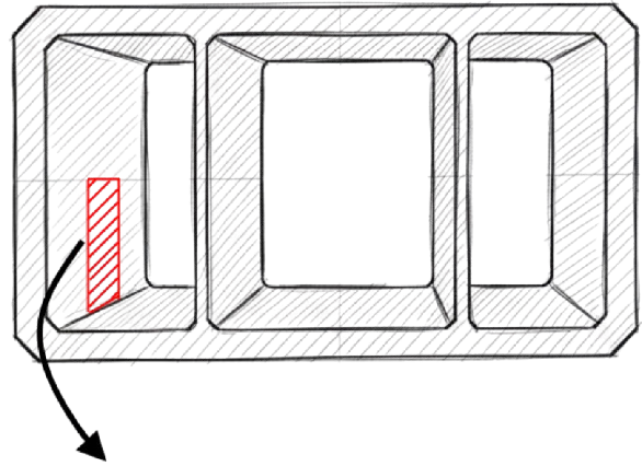
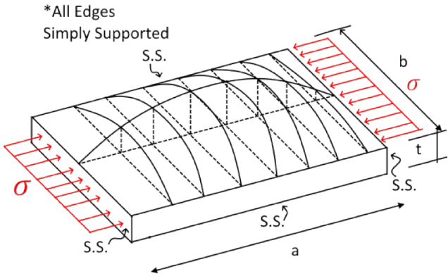
Here I marked a little section of the bridge section, such that you can see how a real-life bridge can be cut down to this simple example, which we have in the calculator.
The first reason why these half sine curves are drawn on the diagram is that it is where the essential Elastic buckling equation stems from. Let me explain.
On this diagram of the plate, if we put a compressive stress on both sides, it will buckle if it is high enough. Imagine now that the compressive stress comes from a force N on both sides. We now want to take this physical case, and simply get an equation to calculate when it buckles, under which compressive stress. Then we can use it as a design tool.
Then, without going too much into detail, the Kirchhoff-love theory, which is (the thin-plate equivalent of Euler-Bernoulli beam theory), and its assumptions
Straightness: Normals to the mid-surface remain straight after deformation.
Perpendicularity: Normals remain perpendicular to the mid-surface (neglecting transverse shear strain).
Incompressibility: The thickness of the plate does not change during deformation.
and combining it with the governing Fourth-order PDE, also called the biharmonic equation (which I will not show here, then it becomes more confusing to the reader than necessary).
Solving this equation using the standard deflection relations to stresses and applied forces, and using the double Fourier Sine Series, then the result of the critical buckling force becomes:
Where
$$\nu = Possion’s Ratio $$
m is equal to the number of half sine waves across the plate width
n is equal to the number of half sine waves across the plate length
So we see that the curves I drew on the diagram represent the buckling modes, and typically m is equal to one because the plate will have its first mode buckle into a single “hump” across the width, because that requires the least energy. It may buckle into multiple humps along the length (n=1,2,3…) depending on whether the plate is short or long.
To convert this equation into stresses, we multiply by the area, and present the mode-dependant terms into a single coefficient, k, which is exactly the plate buckling coefficient.
The final elastic linear plate buckling equation is presented as:
$$\sigma_{cr}=\frac{k\pi^2E}{12(1-\nu^2)}\left(\frac{t}{b}\right)^2 $$
and for shear:
$$\tau_{cr}=\frac{k\pi^2E}{12(1-\nu^2)}\left(\frac{t}{b}\right)^2 $$
This is exactly what the calculator uses.
For reading more about this, I recommend looking into Chapter 5 “Buckling of thin-walled structures” Structural Design from First Principles, by Michael Byfield. He did an incredible job, also showing visualizations in the chapter, so you really get a feel for real structures, where this phenomenon happens.
With this, we can input uniaxial in-plane compression for 4 types of boundary conditions, and in-plane shear for 2 types of boundary conditions.
The output is an elastic critical stress:
$$\text{Compression}: \sigma_{cr} \quad \text{Shear}: \tau_{cr} $$
Then I added, such that we can also find the:
- Critical membrane load for compression and Critical shear flow for shear
- A simple Buckling vs yield comparison, such that we can find utilisation
- A slenderness proxy based on the ratio of yield to elastic critical stress (used for Eurocode 3 checks)
- A “required thickness”, to find the required thickness to have the applied and critical compression stress equal to each other
$$ \sigma_{cr}=\sigma_{applied} $$
$$ \tau_{cr}=\tau_{applied} $$
Geometry, notation, and direction of loading
Inputs use:
- = plate length (mm)
- = plate width (mm)
- = thickness (mm)
The formula in the code is built around b as the “buckling width” in the standard closed-form expression:
So if you increase b, buckling stress drops quickly; if you increase t, buckling stress rises quickly.
Aspect ratio is reported as:
and that is because several Buckling coefficient expressions depend on geometry.
Buckling Coefficient for unstiffened plates
Here i used the table from the book Structural Design from First Principles, by Michael Byfield, inserted below:

Figure 5.6 Page 89, Buckling of thin-walled structures, Structural Design from First Principles, Michael Byfiel
The buckling coefficient k is a compact way to include the effect of:
- edge restraints,
- buckling mode shape assumptions,
- aspect ratio a/b.
In classical solutions, k comes from solving the plate buckling eigenvalue problem with the selected boundary conditions. Different handbooks/tables give different cases and sometimes slightly different approximations. The calculator uses exactly the k-expressions hard-coded in the table above.
I included all of the load cases except the bending load case, because it is not trivial for a user to input a linear varying load, so if you have this situation i recommend using Finite Element Methods if you are comfortable with it.
Buckling vs yield and the slenderness proxy
Elastic buckling theory tells you the stress at which a perfectly elastic plate would bifurcate into a buckled shape.
Real steel plates can:
- yield before they reach elastic buckling (stocky/thick plates), or
- buckle elastically before yielding (slender plates).
So comparing or to a yield measure is a fast “which happens first?” indicator.
In the book Michael Byfiel actually mentions that Thin-walled structures can have a so-called “Post-buckling” reserve of strength, meaning that the failure stress can, in some circumstances, be higher than the elastic critical value. And that is true for shear buckling of stiffened plates. But we don’t have that here, just thought it’s a cool thing. If you wanna learn more about that, the keyword to research for is tension field action.
For compression:
- Yield measure is simply
- Check is:
For shear:
- The calculator uses von Mises relation for shear yield:
- Check is:
Why you might think?
In von Mises yielding, pure shear yield occurs when . It’s a standard way to compare a shear stress to a yield strength defined in uniaxial tension.
Slenderness proxy
The calculator reports a “slenderness proxy”:
- Compression:
- Shear:
This form is widely used as a basic slenderness-type indicator in buckling design because it compares a material strength scale to an elastic buckling scale. Especially in Eurocode 3 (EN 1993-1-1) it is used a lot.
How to interpret it:
- If : elastic buckling stress is below yield → plate behaves “more slender” in this sense.
- If : yield is reached before elastic buckling → plate behaves “more stocky”.
It is not a full Eurocode 3 check that the calculator does, even though that could be cool to implement at some point.
Boundary notation in the calculator
- S = simply supported
- B = built-in / clamped
- F = free
These are idealizations:
- “Simply supported” means rotation is free, but deflection is constrained at the edge.
- “Built-in” means both deflection and rotation are constrained.
- “Free” means neither is constrained (no bending moment or shear reaction at the edge).
Also i implemented a little visualization code in the calculator, such that the user can see how the geometry looks in a 2d plane.
Using This as a Web Buckling Calculator
You can also use the plate buckling calculator as a web buckling calculator by using the calculator as the following:
A beam or girder web is, from a mechanics point of view, simply a plate element. Web buckling is therefore governed by the same theory as plate buckling. This calculator can be used directly as a web buckling calculator by entering the web geometry and choosing boundary conditions that match the real support situation of the web panel.
To model a web:
- Set the plate width equal to the clear web depth between flanges (or stiffeners).
- Set the plate thickness equal to the web thickness.
- Choose the boundary conditions that best represent how the web is supported:
- Webs connected to flanges are often close to simply supported or partially restrained along the top and bottom edges.
- Webs with transverse stiffeners can be modeled as plates with additional edge restraints.
- Select the load case that matches the real behavior:
- Shear for shear buckling of webs in beams and girders
- Compression for axially loaded webs or panel zones
By entering the web dimensions and realistic supports here, this tool directly evaluates the elastic buckling behavior of beam and girder webs.
Conclusion
I have established a Plate buckling calculator for different load configurations and boundary conditions, and i hope it really helps those problems out there in real life. And hopefully you learned something. If you find anything you want me to try and explain or build, don’t hesitate to email me or post a comment.
Sources
Structural Design from First Principles, by Michael Byfiel
Leave a Reply