
PE=π²EI/Le²
λ=Le/r
σE=π²E/λ²
σJ=σy−(σy²/(4π²E))·λ²
A threaded rod in compression can fail in a very sudden way.
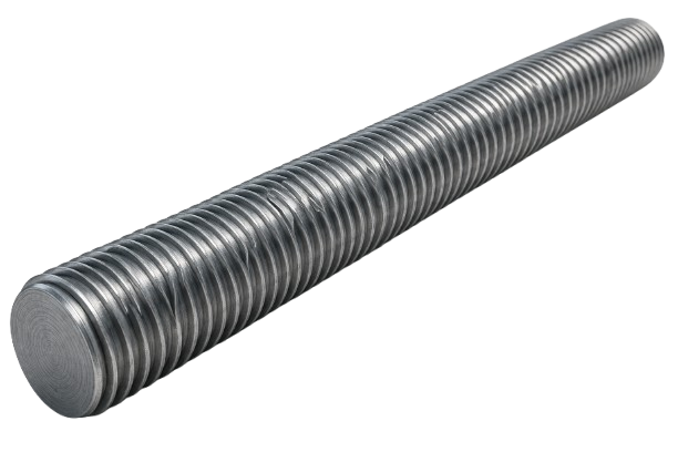
Not because the steel “crushes”, but because the rod loses stability and bends sideways. That is buckling.
This matters for things like jackscrews, leveling feet, machine frames, anchor rods during installation, temporary bracing, and any “long rod between two supports” situation.
A key detail with threaded rods is that the threads reduce the effective stiffness. Buckling strength is extremely sensitive to diameter because the bending stiffness depends on the second moment of area , and for a round rod $$I \propto d^4$$. A small reduction in diameter can mean a big reduction in buckling capacity.
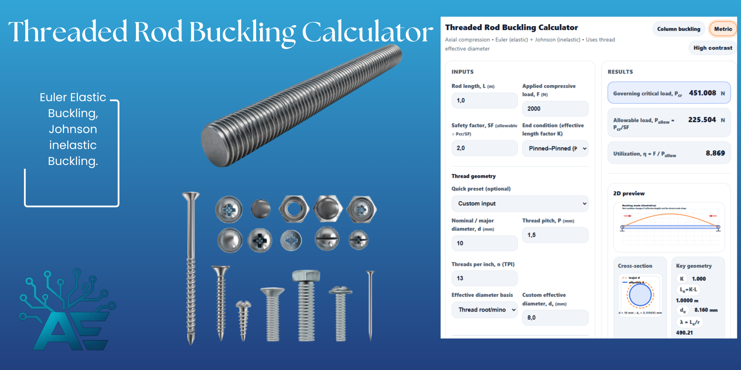
I made this calculator because people often want a fast and practical way to estimate whether a threaded rod is in the danger zone, without setting up a full FE model.
This calculator combines:
- Euler buckling (elastic, slender rods)
- Johnson’s parabolic formula (intermediate rods that start yielding before the Euler mode fully governs)
- A yield cap (it should not predict a “critical load” above the load that would simply yield the section)
It also lets you choose an end condition (via an effective length factor ) and a thread-based effective diameter method.
How to use the threaded rod buckling calculator
Start from the top.
Pick Metric or Imperial in the top-right corner. The calculator converts everything internally and keeps the inputs consistent.
1) Enter the rod length and your applied load
- Rod length L is the unsupported length between end restraints.
- Applied compressive load F is what you expect the rod to carry in compression.
Then set a safety factor (SF). The calculator reports:
and a utilization:
So if , you are above the chosen safety limit.
2) Pick the end condition (K-factor)
This is one of the biggest drivers of buckling.
The calculator uses the classic textbook effective length factor idea:
Pinned–Pinned is the baseline (). Fixed–Free (cantilever) is much more slender (). Fixed–Fixed is much stiffer ().
If you are unsure, it is usually safer to pick a less restrained condition than you hope you have in real life.
3) Define the thread geometry
You can either:
- choose a preset (like M10×1.5 or 1/2-13 UNC), or
- type the nominal diameter and the pitch (metric) or TPI (imperial)
4) Choose how the calculator builds the effective diameter
Buckling depends on bending stiffness, so we need an effective diameter for the circular section used in the math.
You can choose:
A) Thread root / minor diameter (conservative for compression)
For ISO/Unified-style 60° threads, the calculator uses the common “basic” relation:
(where is nominal/major diameter and is pitch).
This usually gives the lowest buckling strength (most conservative), because it is closest to the smallest diameter in the threaded region.
B) Tensile stress area equivalent diameter (often used for bolt tension)
The tensile stress area is a standard bolt concept, and one common ISO metric expression is:
From that, the calculator converts into an equivalent diameter by treating it as a circle with the same area.
For inch threads, a common form is:
where is TPI.
This option will typically predict a slightly higher buckling capacity than the minor diameter option.
C) Major diameter (not recommended)
This is optimistic for a threaded region. It can be useful only if the buckling length is entirely in an unthreaded shank.
D) Custom effective diameter
Use this if you measured the actual minimum diameter, or if you want to represent a special rod shape.
5) Enter material properties
You need:
- Young’s modulus E
- Yield strength σy (compression yield is treated the same as tension yield here)
Then the calculator evaluates Euler vs Johnson and reports the governing critical load.
Threaded rod buckling calculator explained
This section documents exactly what is going on under the hood.
Buckling model and assumptions
The calculator treats the rod as an ideal column:
- straight rod, no initial crookedness
- axial (concentric) compressive load
- linear elastic modulus
- a circular cross-section described by one effective diameter
- end restraint handled by through
Real rods can buckle earlier than this ideal model if the load is eccentric, if there is misalignment, if the rod is not perfectly straight, or if the end condition is softer than assumed.
Effective length and K-factor
Instead of modeling end fixity directly, classical column theory uses an “equivalent pinned column” length:
Typical values (the calculator uses these):
- Pinned–Pinned:
- Fixed–Fixed:
- Fixed–Pinned:
- Fixed–Free (cantilever):
Cross-section properties from the effective diameter
The calculator treats the “buckling section” as a circle with diameter .
Area:
Second moment of area:
Radius of gyration:
For a solid circle this simplifies nicely to:
because .
Slenderness ratio
The calculator uses the standard slenderness ratio:
This is the key geometric “how easy is it to buckle” number.
Big increases . Small increases . Threads reduce , which reduces , which increases .
Euler buckling (elastic critical load)
Euler buckling is the classic result for a slender elastic column:
In stress form, you can write:
That is why slenderness shows up everywhere.
Johnson buckling (inelastic / intermediate columns)
Euler theory assumes purely elastic behavior. But for “less slender” columns, the stress level predicted by Euler may approach yield.
Johnson’s parabolic formula is a practical way to interpolate between yield and Euler behavior:
and the load form is:
The transition slenderness used in many notes is:
If is below that, Johnson is typically used; if is above that, Euler is used. The source for this is from purdue.edu
Yield cap
Even with Johnson, it is useful to also compute the pure yield load of the same effective area:
The calculator then keeps the predicted critical load from exceeding yield:
Governing critical load in the calculator
The selection logic is:
- Compute
- Compute
- If : use Euler
- If : use Johnson
- Then cap with yield:
This gives three reported values (Euler, Johnson, Yield) and one “governing” value .
Allowable load and utilization
With the safety factor:
and utilization:
This is a simple way to see how far you are from instability in the chosen ideal model.
What the visualization is showing
The 2D sketch is a guide:
- the rod is drawn as a straight member
- a buckled curve is drawn on top to represent the expected mode shape for the chosen end condition
- the cross-section sketch shows the major diameter and the effective diameter so you can immediately see what the “thread reduction” is doing to the stiffness
It is not a real deflected-shape solution. It is a visual explanation of the boundary condition and the effective diameter choice.
Practical notes and common pitfalls
A threaded rod in the real world is rarely a perfect Euler column.
Small eccentricity and misalignment matter a lot. If the compressive force is not perfectly concentric, the rod sees bending from day one, and buckling capacity drops.
End restraint is often overestimated. If the ends can rotate even a little, “fixed” behaves closer to “pinned”, and the true is higher.
If your rod is in a joint, the load path might include bending from connection flexibility, washers, gaps, or uneven bearing.
So treat this as a fast screening tool.
If the calculator says you are close to the limit, the right move is usually to improve one of these quickly:
- shorten the unsupported length (add a guide/support)
- increase effective diameter (bigger rod, less threaded length in the buckling region)
- improve end restraint in a real, testable way
- reduce load or add load paths in parallel
Conclusion
This threaded rod buckling calculator estimates critical compressive capacity using Euler buckling for slender rods and Johnson buckling for intermediate rods, with end conditions handled through an effective length factor and stiffness handled through a thread-based effective diameter.
If you have a setup where the rod is long, lightly restrained, and truly in compression, this is exactly the situation where buckling can surprise you.
If you are interested in more specific calculators that are easy to use, feel free to email me or leave a comment.
Sources
- Ansys Innovation Space — Linear column buckling lesson (effective length factor examples, incl. fixed–pinned K≈0.699)
- Purdue University (ME 323) — Column buckling notes (Euler vs Johnson selection using slenderness)
- SolidWorks Help (2025) — Tensile stress area formulas for bolts (metric/ISO form)
- Vargus — ISO metric thread dimensions PDF (includes basic relations such as minor diameter using 1.22687·P)
- Euler’s critical load (formula and assumptions)
- Johnson’s parabolic formula (stress form and critical slenderness ratio)
Leave a Reply